Altitude Hold Setup Using SU04 via I2C with Crossflight/Crossflight-CE, Mini Pix, and PIXHAWK
(Open-Source Firmware v4.3 and Above)
Configuration Instructions (Altitude Hold Function)
- Connect the SU04 to the flight controller.
- In the full parameter list, search for
RNGFND1_. As shown in the figure below, setRNGFND1_TYPEit to 2, then click Write Parameters. - After power cycling the flight controller, it will successfully recognize the SU04.
- (Note: Starting from firmware version 4.3, the flight controller has a longer boot time. When using an older ultrasonic sensor, you need to power the flight controller with a battery first, and then immediately plug in the ultrasonic sensor to ensure a successful connection.)
- Set the following parameters:
RNGFND1_MAX_CMto 450RNGFND1_MIN_CMto 43 (unit: cm)RNGFND1_ORIENTto 25
Parameter Descriptions
RNGFND1_MAX_CM: The maximum distance that the flight controller can recognize from the module in altitude hold mode.RNGFND1_MIN_CM: The minimum distance that the flight controller can realize from the module in altitude hold mode.- When the distance reported by the module is outside the range of 43–450 cm, the flight controller will not use the module data and will instead rely on the barometer for altitude hold.
Viewing Ultrasonic Sensor Data
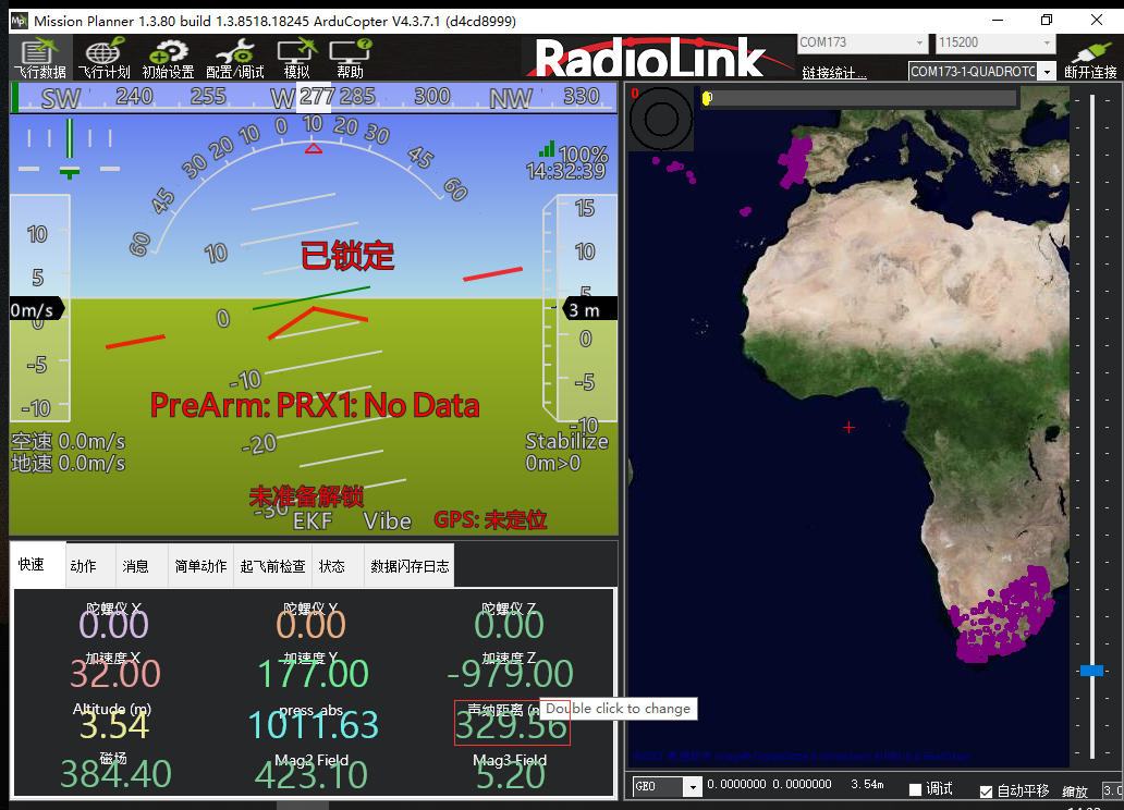
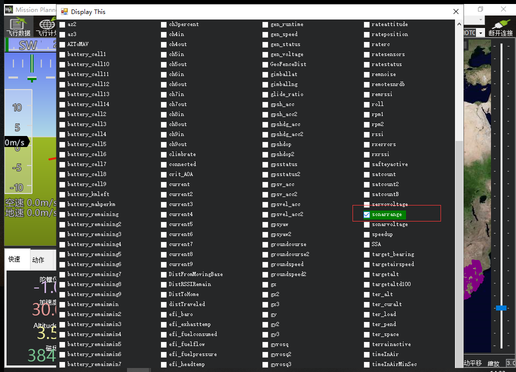
1. Viewing ultrasonic data in the Quick interface
Connect the flight controller to the Mission Planner. In the Quick interface, double-click the tab to bring up a large list. Select sonarrange, and the ultrasonic height data will be displayed in that position.
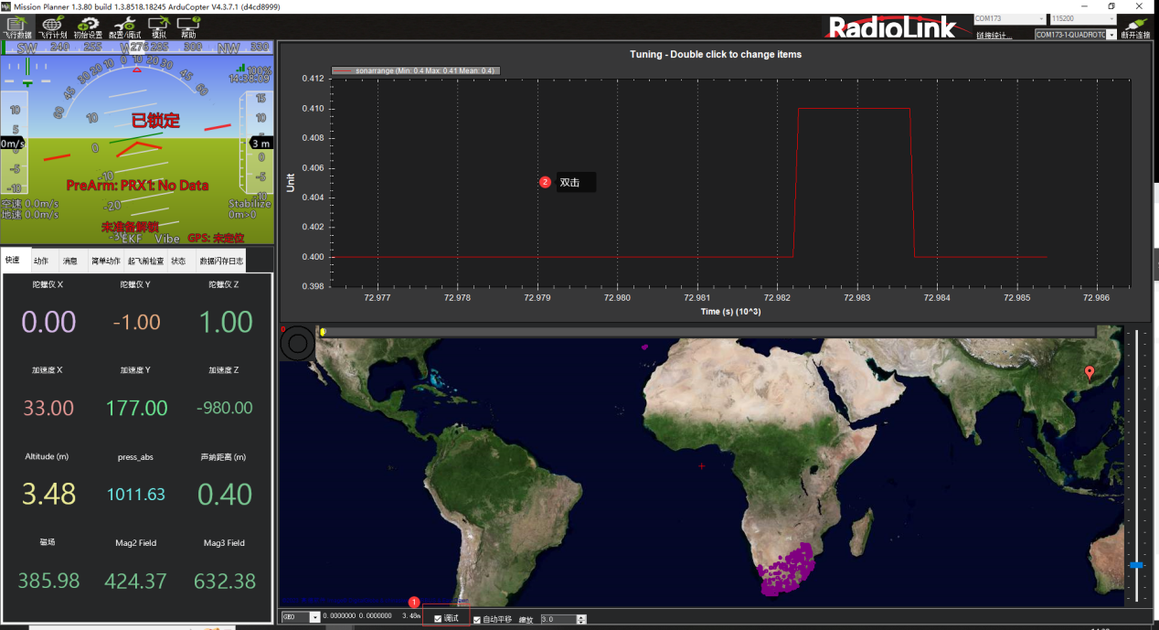
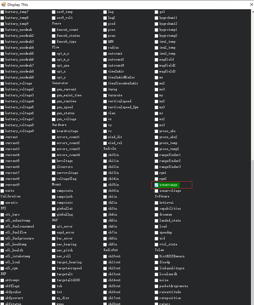
2. Viewing ultrasonic data in the Debug interface
Enable the debug option in the ground station. Double-click the pop-up dynamic table, select sonarrange from the list, and the real-time waveform of the ultrasonic data will be displayed, as shown in the figure below.